Manual coupling systems
Description
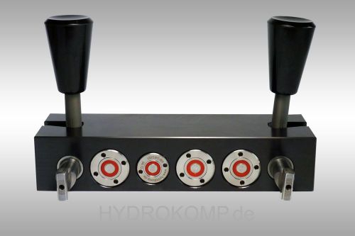
Manual coupling systems are applied with machine tools that operate with hydraulic fixtures but do not have a standard equipment of a hydraulic interface for oil supply to the fixture pallet. The operating personnel take care of coupling and decoupling. In contrast to quick-locking couplings, manual couplings do not bear the danger of mixing up pressure line and tank line. Also, the coupling process is made much faster. After clamping the workpiece it is easy to unclamp the system without effort by the use of a hydraulically piloted check valve. Also the system pressure remains. To unclamp the system the T-port must be pressurized. At the single-acting coupling system the ball valve takes this feature.
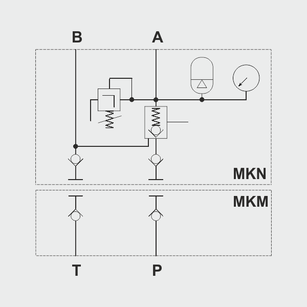
Required safety elements are already integrated. These include one hydraulic accumulator, one check valve and one pressure relief valve which protects the hydraulic accumulator from a pressure rise over 10%. The coupling unit can be equipped with two different hydraulic accumulators. HYDROKOMP recommend the accumulator with 13 cm³ nominal volume up to an oil volume of approx. 100 cm³ in the fixture. When the required oil volume is larger, the hydraulic accumulator with 40 cm³ nominal volume should be applied. The hydraulic accumulators are subject to technical rules for pressure vessels. As standard the manual coupling systems are equipped with manifold and G1/4 threaded ports for oil supply. All flange-on surfaces have O-ring counter-bores on the bottom and on the rear side, which also allow oil supply without pipes through drilled ducts.
-
versatile mounting options
-
safety elements are integrated
-
no mixing up of pressure line and tank line
-
quick and easy coupling
-
system pressure remains during coupling
-
standard systems and special designs available
![]()
Safety information:
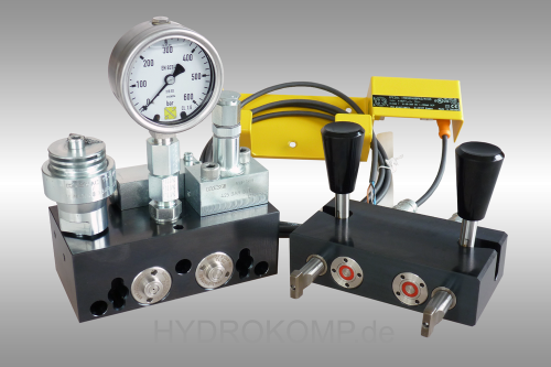
A safety holder with an inductive proximity switch is optional available for the double-acting coupling system. The safety retainer keeps the coupling mechanism board in the decoupled state into a parking station. Through the integrated proximity switch the safety holder can be directly connected with the machine control. With that, the pallet transport is only permitted in decoupled state. With the help of a equalizer valve in the coupling nipple of the T-port the pressure rise is limited to about 5 bar in decoupled state, eg. when a leakage in the system occurs. For coupling and uncoupling of the coupling nipple unit and the coupling mechanism board both hydraulic lines must be depressurized by the hydraulic valves.
Application examples
Data sheet 100-2
Nominal diameter:
5 (coupling elements)
Operating pressure:
pmax. 500 bar
Design:
coupling unit with lever or ball valve
Operating method:
single-acting or double-acting
Oil supply:
threaded port G1/4 or manifold with O-ring
Hydr. accumulator:
13 cm³ or 40 cm³
![]()
Data sheet (PDF):
System components:
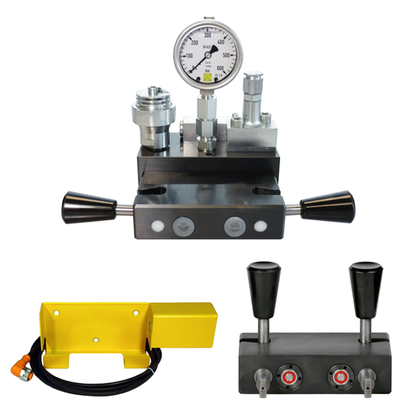
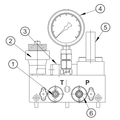
Coupling nipple unit (MKN)
1. Coupling nipple with pressure relief valve
2. Hydraulic accumulator 13 cm³ or 40 cm³ (optionally)
3. Hydraulically operated check valve Qmax. = 20l/min
4. Pressure gauge up to 600 bar
5. Pressure relief valve, opening pressure 425 bar
6. Coupling nipple for depressurized coupling
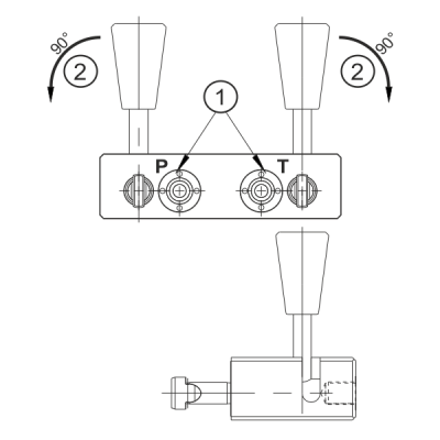
Coupling mechanism board (MKM)
Coupling mechanism board, which locks both components for pressure transfer. Both tension rods are inserted into the bayonet catch. Then the levers are turned to the side by 90°. Through two integrated drafts the tension rods are shortened and the coupling process is executed. The locking stroke is 5 mm.
1. Coupling mechanisms
2. Levers for locking the modules
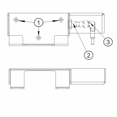
Safety holder (MKS)
Safety holder with inductive proximity switch and plug (cable length 3 m). The safety holder takes up the uncoupled coupling board into a parking station.
Through the integrated proximity switch the safety holder can be directly connected to the machine control. So, the pallet transport is only permitted in uncoupled state.
1. Hole with counterbore DIN 74 - F4
2. Inductive proximity switch
3. Plug with cable
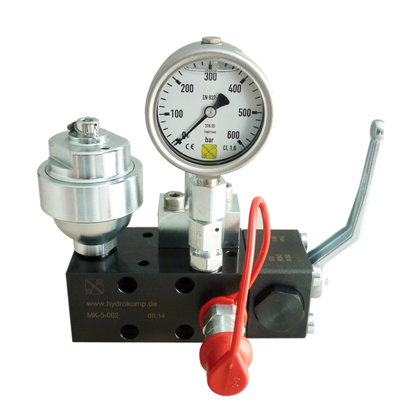
Coupling unit with ball valve (MK)
The coupling unit can be connected optional at factory
by flange-bottom, flange-rear or rear threaded port.
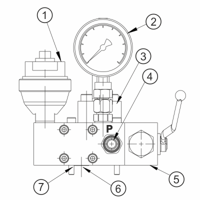
1. Hydraulic accumulator 13 cm³ or 40 cm³ (optionally)
2. Pressure gauge up to 600 bar
3. Pressure relief valve, opening pressure 425 bar
4. Flat face plug with dust cover
5. Ball valve
6. Port Ø5 mm, O-ring or screw plug
7. Cap head screws DIN 916, M6x60 (not included)


