Block cylinders, piston with internal thread

Description
Block cylinders are popular design elements in all areas where very powerful short strokes are required. Block cylinders have internal piston rod threads for secure screw-in contact bolts. Their compact cubic shape facilitates attachment and guarantees high operating pressures. Various versions of hydraulic oil feed cover the whole range of applications.
The HYDROKOMP block cylinders offer technical advantages in the area of the seal at the piston-rod end. A double hydraulic seal is used here as standard, guaranteeing extremely low leakage in continious operation. All block cylinders are also equipped with a metal wiper ring, which prevents any metal shavings from penetrating into the soft wiper ring.
double-acting:
The double-acting function permits precise stroke times as the piston is extended and retracted. Extension and retraction strokes are force-actuated.
single-acting:
HYDROKOMP offers single-acting block cylinders with or without spring return. With a spring reset function the piston is pulled by the spring into the start position when depressured. Block cylinders without reset spring do not have an automatic piston return.
-
ideal for continuous operation
-
space-saving installation
-
four mounting options
-
metal wiper as standard
-
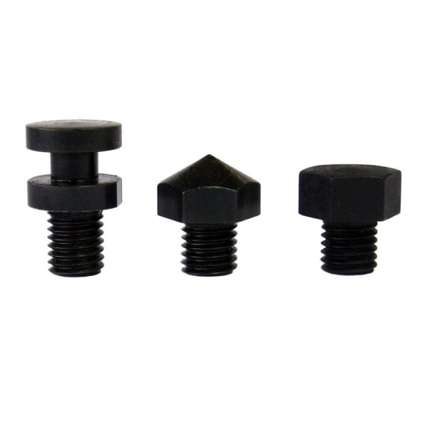
internal piston threads for secure screw-in eg. contact bolts
-
standard cylinders and special design available
![]()
Exemplary design of a block cylinder
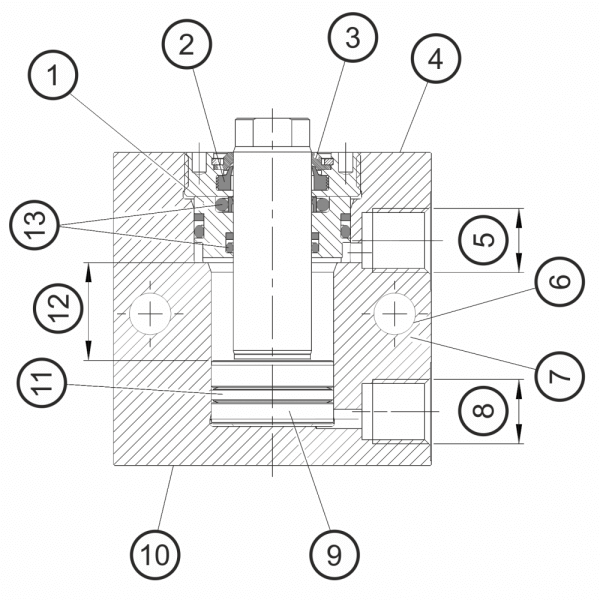
double-acting
2. soft wiper
3. metal wiper
4. rod side
5. port, retract
6. lengthwise and crosswise bores
7. cylinder housing
8. port, extend
9. piston
10. bottom side
11. piston sealing
12. piston stroke
13. rod sealing
Application example
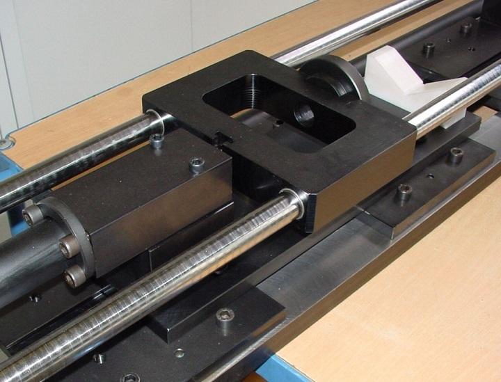
The picture shows a press-in fixture that mounts bearings on shafts. The block cylinder used has a stroke of 100 mm, in order to bridge the distances involved. Because of the wide variety of tools, the carriage can be ranged appropriattely with the block cylinder. Supports of various lengths are mounted axially behind the block cylinder for this purpose. This results in only minimal bending forces being passed to the overall structure.
One special feature of the fixture lies in the pressure lowering function of the manual pressure pump. After the bearings have been preassembled they are secured mechanically under pretension. For this purpose the assembly pressure is released to approx. 60 bar by means of a manuall ball valve and a downstream pressure limiting valve.
Data sheet 200-3
Operating pressure:
pmax. 500 bar
Operating method:
single-acting or double-acting
Piston Ø:
16, 20, 25, 32, 40, 50, 63, 80 and 100 mm
Stroke:
numerous strokes from 8 up to 200 mm
Thrust force:
from 2 kN at 100 bar up to 392 kN at 500 bar
Traction force:
from 1,2 kN at 100 bar up to 237 kN at 500 bar
Oil supply:
threaded port G1/4 or G1/2 or manifold with O-rings
Sealing:
NBR -10°C up to +80°C, FKM up to 150°C
Wiper:
soft wiper and metal wiper
Data sheet (PDF):
Designs:

Type A
threaded port G1/4 or G1/2
Mounting bores
in the housing
lengthwise and crosswise

Type C
manifold port with O-ring, rod side
Mounting bores
in the housing lengthwise

Type D
manifold port with O-ring,
bottom side
Mounting bores
in the housing lengthwise
fig. 1 variant „standard“
fig. 2 variant „centered bore“

Type E
manifold port with O-ring, broadside
Mounting bores
in the housing, crosswise
Product configurator:
- generate an order number
- request a quote