Rotary valve couplings
Description
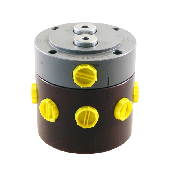
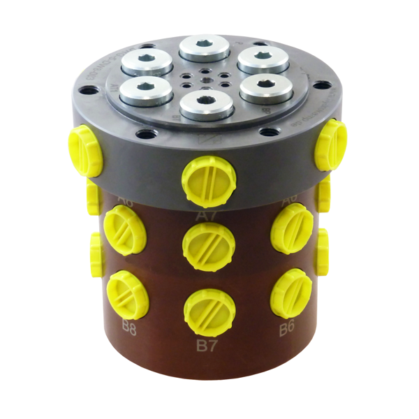
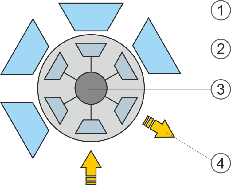
Rotary valve couplings transmit hydraulic fluid to revolving tables. The structure is designed as a rotary slide valve, which permits several hydraulic devices to be supplied simultaneously with hydraulic fluid under pressure, and independently of that, a loading and unloading station to clamped or unclamped by means of distributing valves.
-
axial and radial connections in the piston
-
single-acting or double-acting
-
designed with up to 10 stations
-
1 or 2 stations for loading/unloading
-
for seperately or simultaneously triggering
-
standard rotary valve couplings and special designs available
![]()
Important operating instruction:
The rotary valve coupling must only be operated with hydraulic fluid. All levels must be connected to the pressure generator in order to guarantee lubrication of the seals. Operation must only be carried out with the screw connections fitted. Rotary valve couplings should only be used for phased operation.
Mounting instruction:
The rotary valve coupling must only be operated with hydraulic fluid. All levels must be connected to the pressure generator in order to guarantee lubrication of the seals. Operation must only be carried out with the screw connections fitted. Rotary valve couplings should only be used for phased operation. The Rotary Valve Coupling must be fitted in such a way that no bending moment is exerted on either the stationary or the rotating component. It has proven effective to bolt the rotating housing with the connectors to the clamping devices and merely to secure the standing piston against twisting (prevent initiation of bearing forces). Only hoses should be used for the pipe connection between the torque brace and the rotary piston.
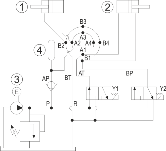
At an operating pressure of about 200 bar and above, it is recommended that a hydraulic accumulator with a storage-safety device be fitted between the check valve and connector level A (permanent pressure area). This accumulator is for the purpose of compensating for minor fluid loss through leakage, when the machine is at rest in the loading and unloading station. You are recommended to use only directional valves to control the rotary valve coupling.
Specimen circuit:
Application examples
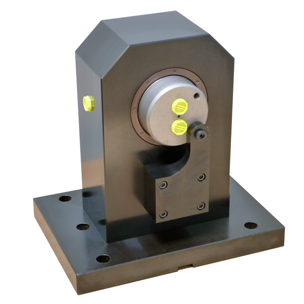
Steady bearing with integrated rotary valve coupling
Besides the possibility to make multiside machining also multiple clampings can be realized (depending on the workpiece). For that, due to clamping quality and effectiveness hydraulic elements should be applied.
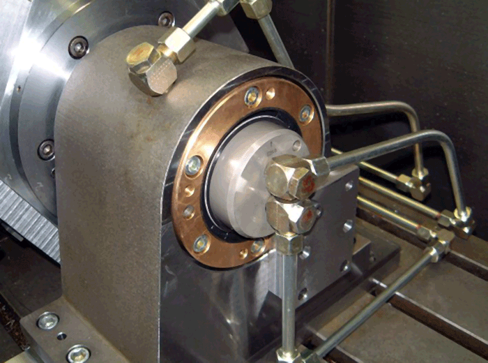
For oil supply HYDROKOMP has developed a steady bearing which combines bearing, bearing clamping and rotary valve. Above that the rotary valve is equipped with a control function which allows clamping and releasing only in a defined position.
Another advantage is the characteristic that the bearing clamping can be supplied with the same hydraulic pressure as the clamping elements. That way it is not required to reduce pressure at the hydraulic aggregate.
With this construction the space requirement for the clamping device can be maximized, the one for the steady bearing can be minimized and the costs for hydraulic and electrical controls can be optimized.
Rotary valve coupling in a support bearing of a reversible clamping device
Cost pressure, time pressure, flexbility, quality standards, reduction in non-productive time, set-up time, all catchwords with which a production company is confronted in everyday operations and terms that formulate objectives. In this case a high number of items were to be machined annually, in production batches of 60 in one clamping.
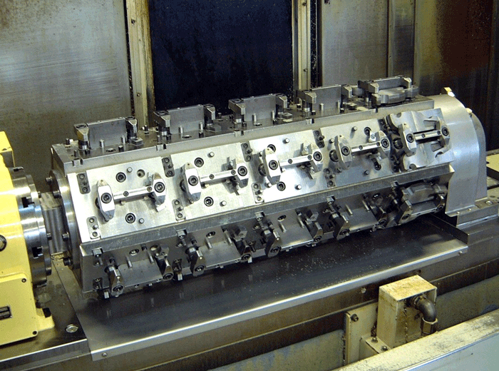
The most useful clamping solution was a multible rotary clamping fixture, which permits both multilateral machining of the workpieces and multiple clamping. This solution was substantially determined by the use of the existing machine tools with a vertical spindle.
HYDROKOMP was commissioned as a manufacturer of hydraulic clamping elements to design this device. For this purpose a clamping concept was developed in advance, together with production planning.
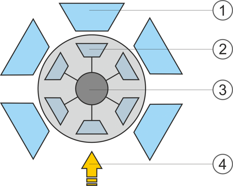
A rotary valve coupling is installed in the counter bearing, so that only the upwardly facing side of the fixture can ever be clamped or unclamped.
Advantages of many types are offered by this design principle. Using normal rotary couplings, it would be necessary to employ a six-way rotary coupling. This requires more space and generates more kinetic torque as a result of the necessary seals.
There are additional costs because each connection plane must be fed by means of a hydraulic distribution valve including electrical control unit. This makes it possible to provide five sides of the fixture with constant pressure and to clamp and unclamp hydraulically only the sixth side facing upwards.
Data sheet 500-4
Nominal diameter:
5
Operating pressure:
pmax. 350 bar
Operating temp.:
from -10°C up to +60°C
Flow rate:
max. 133 cm³/s (8 l/min) in AT and BP
Stations:
6, 8 or 10
Triggering:
separetly or simultaneously
Oil connection:
G1/4 threaded port in the housing and rotary piston, radial
manifold with O-ring in the rotary piston, axial
Design:
for single-acting or double-acting clamping elements
![]()
Data sheet (download here) and step files on TraceParts:
Designs:
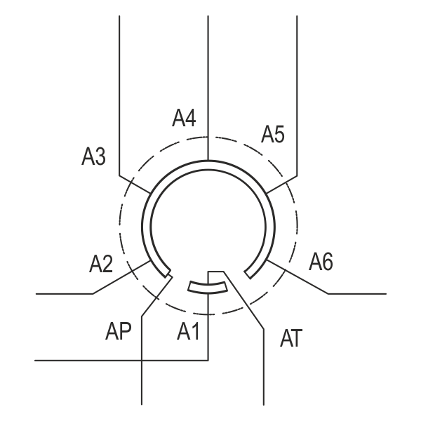
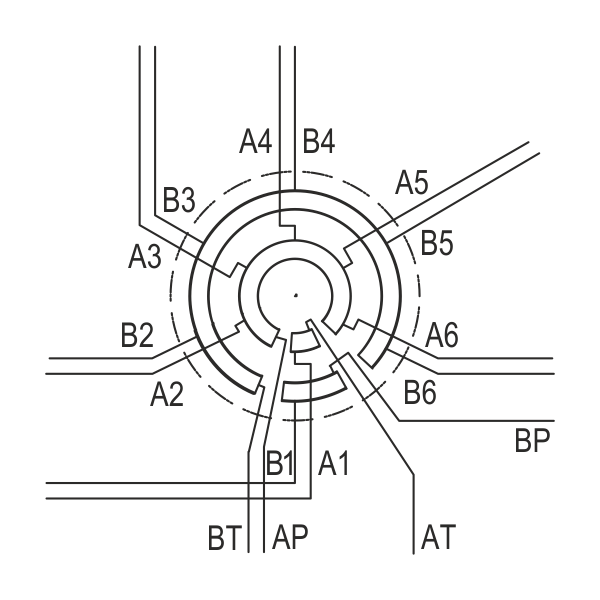
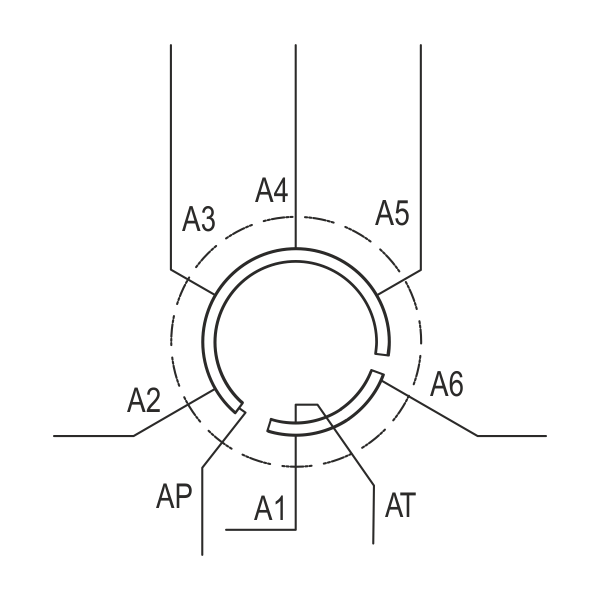
Rotary valve coupling, 1 station loading/unloading
1 station (loading/unloading)
Circuit description:
AT to A1
AP to A2 – An
BP to B1
BT to B2 – Bn
Rotary valve coupling, 2 stations loading/unloading, triggered simultaneously
2 stations (loading/unloading)
Circuit description:
AT to A1 + An
AP to A2 – An-1
BP to B1 + Bn
BT to B2 – Bn-1
Rotary valve coupling, 2 stations loading/unloading, triggered separetely
2 stations (loading/unloading)
Circuit description:
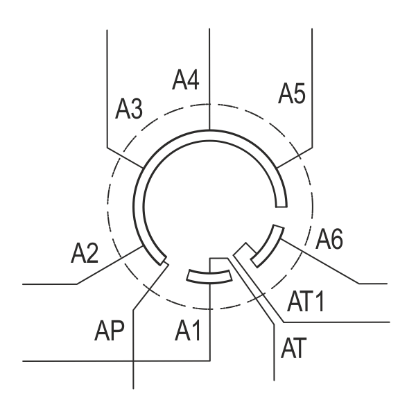
AT to A1
AT1 to An
AP to A2 – A-1
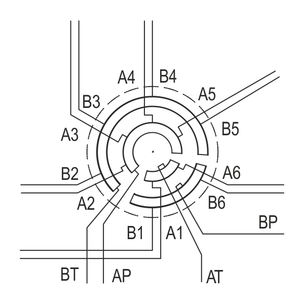
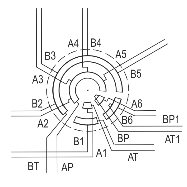
2 stations (loading/unloading)
Circuit description:
AT to A1
AP to A2 – An
BP to B1
BT to B2 – Bn
![]()


