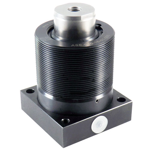
Work supports, with thread and bottom flange plate
Work support element,
plunger diameter 40 mm,
plunger stroke 18 mm,
G1/4 threaded port
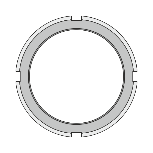
Nut,
for the installation
of the work supports
into the fixture via thread
(Accessories)
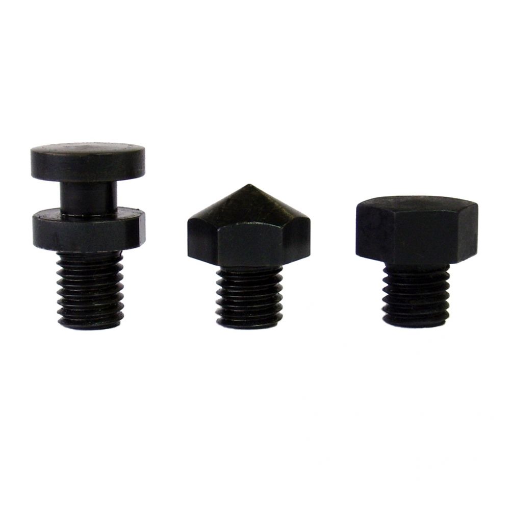
Contact bolts,
for screwing into the
internal thread of
the piston rod
(Accessories)
Description
In these work supports a spring advance the plunger against the workpiece. The spring force can be adjusted by an integrated set screw. Ensure that the workpiece cannot be lifted by the adjusted spring force. A contact bolt can be screwed into the internal thread for height adjustment. Oil is supplied by a lateral G1/4 threaded port or a manifold connection in the lower flange plate. The hydraulic fixing of the plunger can be combined with the hydraulic clamping of the workpiece or separated.
-
various installation options
-
plunger with internal thread for screwing spacer elements eg. contact bolts
-
plunger fixing combined with clamping or separate possible
-
spring force adjustable via integrated set screw
-
standard work supports and special designs available

![]()
Safety instruction:
Transverse forces cannot be absorbed by the work support. Always center load over work support. Clamping force and support force must be matched. A ventilation line must be connected, if there is a risk of fluid ingress into the work support during machining. The internal thread of the plunger has to be protected against contamination by a seal plug or screw-in element. Screw-in elements with a large mass may affect the function of the work support.
Data sheet 280-10
Operating pressure:
pmax. 500 bar
Advance method:
basic plunger position extracted, plunger retraction against spring force
Plunger:
Ø 32 mm, stroke 16 mm or Ø 40 mm, stroke 18 mm
Min. pressure:
recommendation 100 bar
Support force
max. 60 kN at 500 bar
Advance force
stroke depending 40 N at 100 N
Oil connection
G1/4 threaded port or manifold with O-ring
Wiper:
soft wiper and metal wiper


