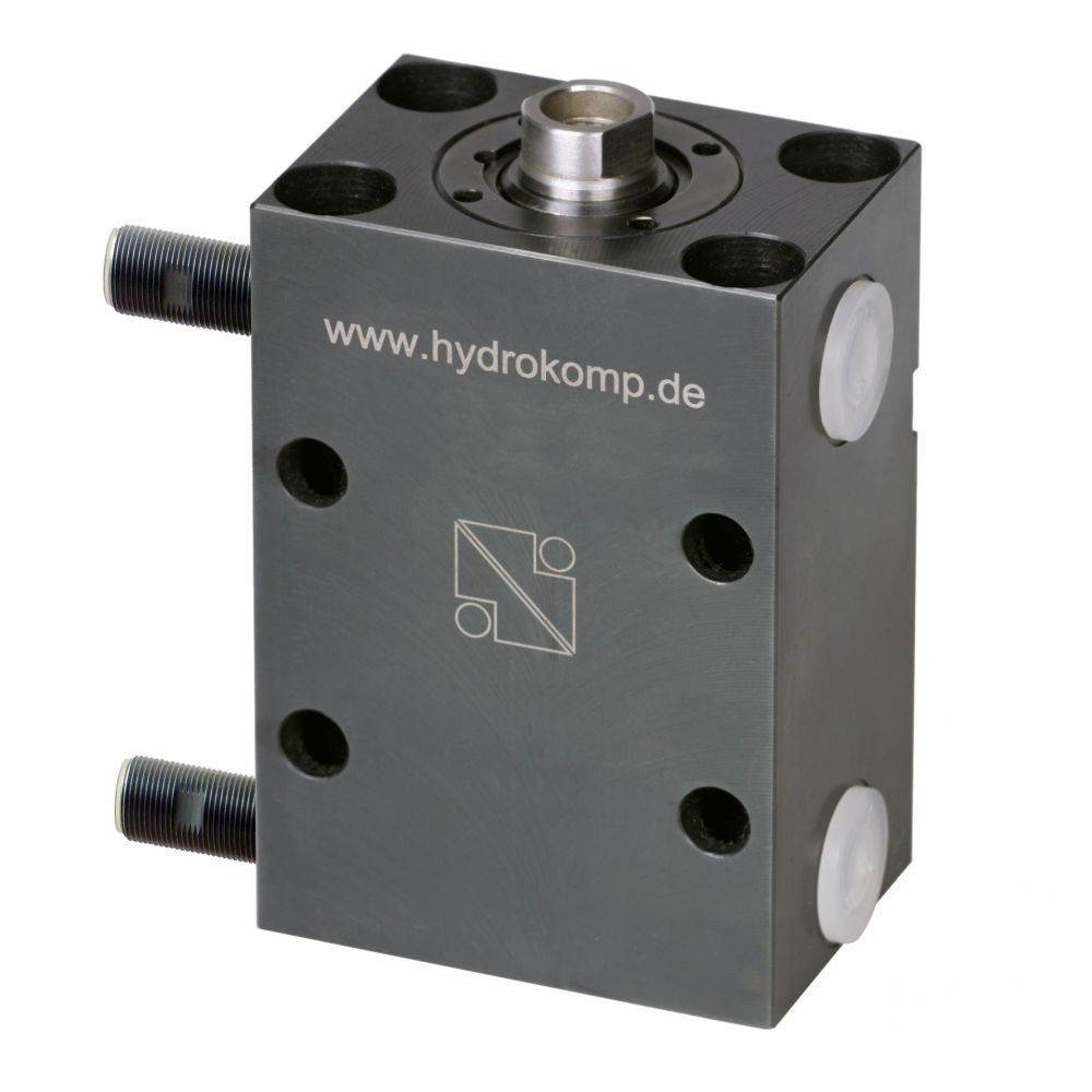
Block cylinders, with end position control
Plug for sensors,
angular or straight
(Accessory)
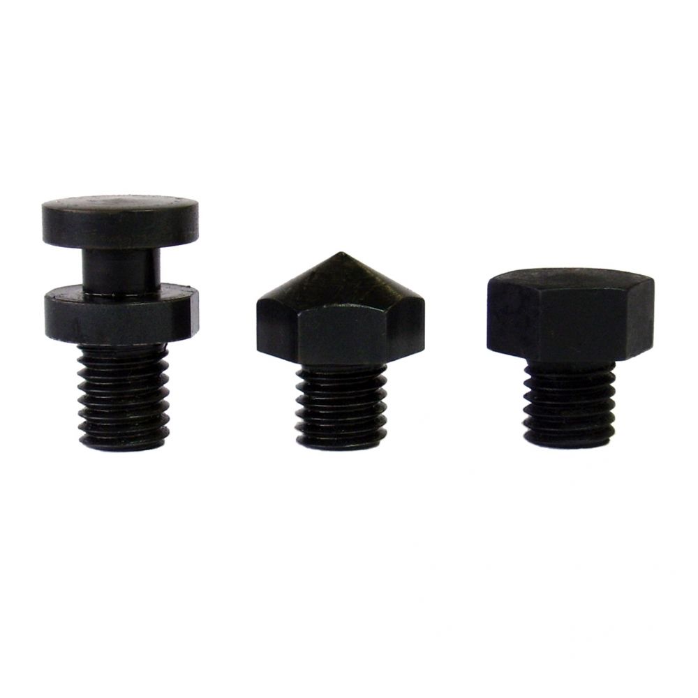
Contact bolts,
for screwing into the
internal thread of
the piston rod
(Accessories)
Description
When time or tact dependent clamp/release processes are essential, the advantages of this block cylinder with end position control become effective. It is ideal for the application in automated plants. The position of the cylinder head is read through the end position control. To do so, the block cylinder has two inductive sensors. These are located in the housing, in the end position of the piston.
Depending on the variant, the sensors are equipped with LEDs. Matching plugs must be ordered separately. There are angled and straight plugs available. Both versions are supplied with 2 m connection cable. The block cylinders have internal piston rod threads for secure screw-in contact bolts. Their compact cubic shape facilitates attachment and guarantees high operating pressures. Various versions of hydraulic oil feed cover the whole range of applications.
HYDROKOMP offers the block cylinders in 9 sizes. and with different variants of the pressure oil supply. We also design and manufacture customized special variants.
-
ideal for automated plants
-
space-saving installation
-
three mounting options
-
metal wiper as standard
-
high monitoring precision
-
standard cylinders and special design available
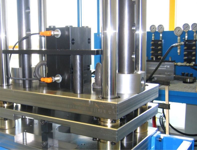
Application example
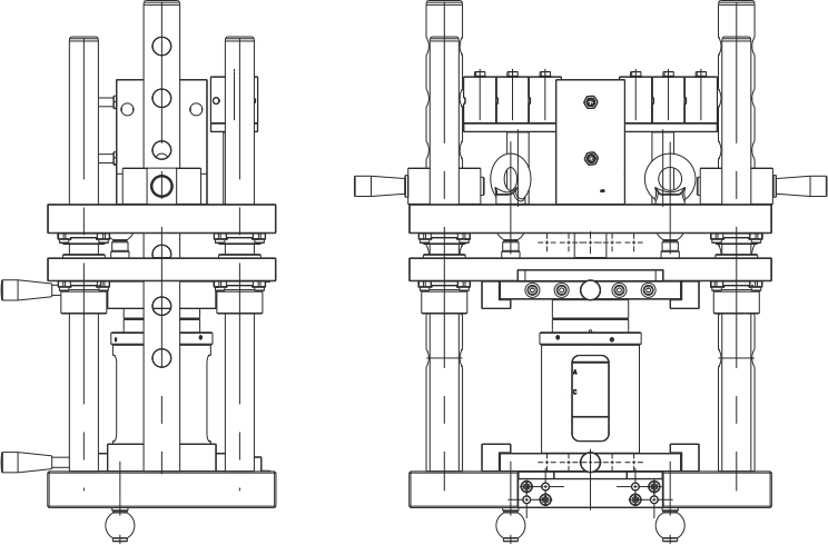
HYDROKOMP developed the above shown test fixture for coupling systems. On the lower fixture plate the coupling plates to be tested are plugged hydraulically. On the upper fixture plate the coupling nipple plates are fastened. The block cylinder descends the upper fixture plate and links up both systems.
The link-up process of the cylinder piston is controlled by the inductive sensors. Once the piston is completely protracted and the coupling process is therefore completed, the system is pressurized and checked for proper operation.
Data sheet 200-10
Operating pressure:
pmax. 500 bar
Operating method:
double-acting
Piston Ø:
16, 20, 25, 32, 40, 50, 63, 80 and 100 mm
Stroke:
numerous strokes from 16 up to 160 mm
Thrust force:
from 2 kN at 100 bar up to 392 kN at 500 bar
Traction force:
from 1,2 kN at 100 bar up to 237 kN at 500 bar
Oil supply:
threaded port G1/4 or G1/2 or manifold with O-ring
Sealing:
NBR -10°C up to +80°C, FKM up to 150°C
Wiper:
soft wiper and metal wiper
Data sheet (PDF):
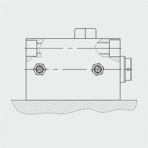
Designs:
Type A
threaded body G1/4 or G1/2
Mounting bores
in the housing
lengthwise and crosswise
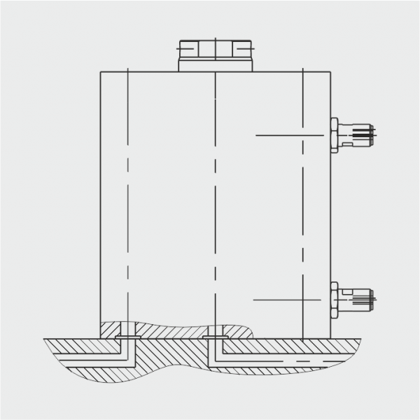
Type D
manifold with O-ring,
bottom side
Mounting bores
in the housing lengthwise
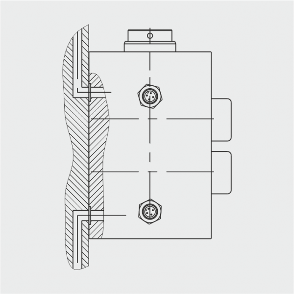
Type E
manifold with O-ring, broadside
Mounting bores
in the housing, crosswise


