Clamping arms for swing clamps
Description
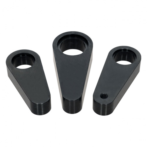
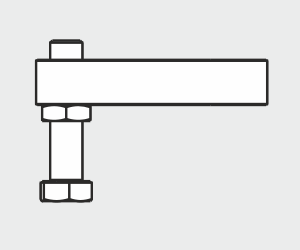
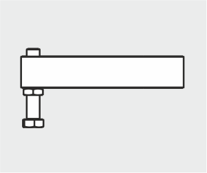
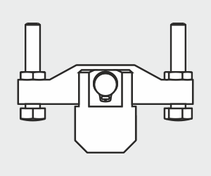
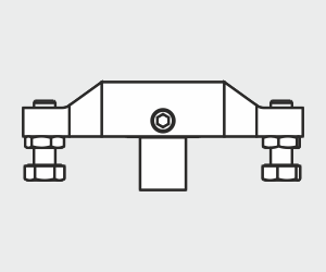
HYDROKOMP offers a wide range of standard clamping arms as an accessory for our swing clamps. The portfolio includes single and double clamping arms with and without contact bolt. Blanks for the production of individual special clamping arms are also available.
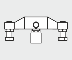
Clamping arm designs:
(Clamping arm holders see data sheet)
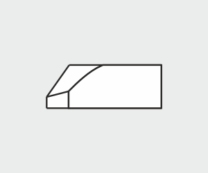
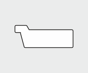
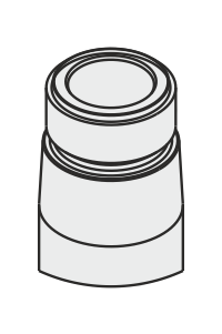
- for taper (SPK)
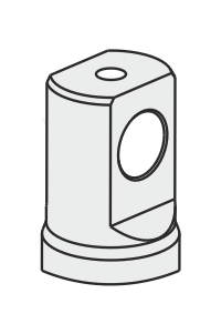
- for pendulum (SPP)
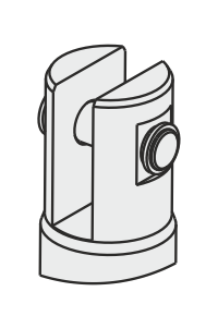
- for clevis (SPG)
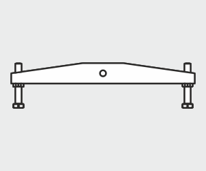
Single clamping arms:
Double clamping arms:
Which clamping arm for which swing clamp?
| Swing clamps (SSZY) | Clamping arms | ||||||||||
|---|---|---|---|---|---|---|---|---|---|---|---|
Design | Data sheet | Webcode | a | b | c | d | e | f | g | h | j |
| A | 240-1 | 024001 | X | X | - | - | - | - | - | - | - |
| B | 240-2 | 024002 | X | X | - | - | - | - | - | - | - |
| D | 240-3 | 024003 | X | X | - | - | - | - | - | - | - |
| A | 240-10 | 024010 | - | - | X | X | X | X | - | - | - |
| A | 240-20 | 024020 | - | - | - | - | - | - | X | X | - |
| B | 240-30 | 024030 | - | - | X | X | X | X | - | - | - |
| C | 240-30 | 024030 | - | - | X | X | X | X | - | - | - |
| F | 240-40 | 024040 | - | - | X | X | X | X | - | - | - |
| D | 240-50 | 024050 | - | - | X | X | X | X | - | - | - |
| E | 240-60 | 024060 | - | - | X | X | X | X | - | ||
| A | 240-70 | 024070 | - | - | - | - | - | - | - | - | X |
Application of special clamping arms:
Special clamping arms are available on request.
To dimension special clamping arms it is important to keep with the clamping force, indicated on the data sheet of the selected swing clamp cylinder. The assigned operating pressures may not be excessed. Once the length of standard clamping arms is to be exceeded, operating pressure and volume flow have to be reduced according to the data in the diagram on the data sheet.
Mounting instructions
Instruction for assembly/disassembly clamping arms:
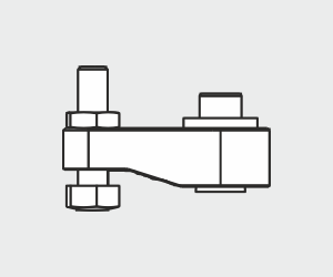
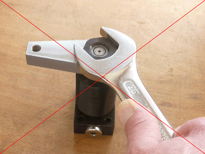
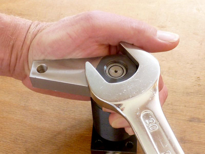
During the mounting of the clamp arm, make sure that torques are transferred in the piston rod. Hold against the clamp arm when you tighten or loosen the tightening screw (see figure).
For swing clamps with overload protection, the function must first be tested. To do this, turn the piston until you feel the overload protection engage. The swing clamp has three ratchet points spaced at 120° intervals.
Normally the mounting of the clamp arm is done in the depressurised state, as described in. However if the clamping arm must be positioned in a precise clamping position, the swing clamp must be applied with pressure at connection A and the piston retracted. Finally position the clamping arm in the intended clamping position on the clamping arm holder. After positioning the clamping arm on the holder, tighten the fastening screws by hand. Then, tighten the fixing screws with a suitable tool.
Carry out the clamping process several times to check if the clamping point and the clamping stroke agree as intended.
After several clamping cycles the torque must be check again at the fastening screws. This prevents the clamping arm from loosening.
Data sheet 240-0
Data sheet (PDF):
Selection guide:
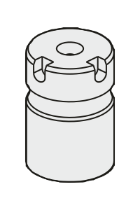
Clamping arm holder:
Note the information about the clamp arm holder and the effective clamping force depending from operating pressure on the data sheet of the selected swing clamp cylinder.
![]()


