Founded 1998, HYDROKOMP designs, manufactures and distributes hydraulic components, coupling systems and clamping technology for mechanical engineering, fixture construction, tooling and many other branches of industry also for different operating conditions.
Sequence valves
Description
The sequence valves are used in the clamping hydraulics as a directly controlled sequence valve. The compact design allows space-saving installation directly in the fixture. The sequence valve is a poppet valve which operates without leakage oil compared to a spool valve. The inlet and outlet pressures of the sequence valves are always identical. As a result this type of valve is ideal for use in sequence control systems. With single-acting cylinders, only one supply line from the pressure supplier (see data sheet 430-1) is required for operation. The design allows valve combinations that can be flanged together to form a block using a common P-connection and standard parts.
-
space-saving installation options
-
quick installation due to flange
-
ideal for pressure sequence control
-
operation with one supply line possible
-
valve combinations possible
-
Integrated check valve
Valve combinations:
Combinations of sequence valves are assembled from an inlet valve (P) and a maximum of four flange-mounted series valves. These are supplied with pressure oil through holes. Sealing between the valve housings is provided by O-rings. In order to ensure proper functioning with sequence controls, there should be a certain minimum pressure difference from valve to valve..
The drawing shows symbolically a clamping device as it can be used e.g. in manufacturing. When pressure is applied, the single-acting cylinder [1] clampes.
When the set opening pressure has been reached, the inlet valve [A1] opens and actuates the swing clamp [2].
The support element [3] clamps the support piston as soon as the opening pressure in the series valve [A2] is reached.
The series valve [A3] actuates the swing clamp [4] to complete the clamping process.
When the device is released, the pressure oil flows back to the pressure generator via the integrated check valves.
Data sheet 700-2
Designs:
threaded type, threaded port, manifold connection with O-ring and valve combinations
Operating pressure:
pmax. 500 bar
Volume flow:
max. 12 l/min
Adjusting range:
15-80 bar, 30-160 bar, 60-315 bar, 100-500 bar
Pressure change
per revolution:
9 (15-80 bar), 15 (30-160 bar), 32 (60-315 bar), 49 (100-500 bar)
Combinable:
inlet valve + max. 4 sequence valves
Oil supply:
threaded port G1/4 or manifold connection with O-ring
Pressure medium:
hydraulic oil according to DIN 51524 Tl.1 up to 3; ISO VG 10 up to 68 nach DIN 51519
Data sheet (PDF):
Directly controlled sequence valve designs:
Threaded type
G1/4 threaded port
Manifold connection with O-ring
Valve combinations:
Inlet valve with threaded connection
Series valves with threaded connection
Request a quote / 3D models
Pressure pump-units, air-hydraulic
Description
These pneumatic hydraulic pressure pumps are suitable for application in simple clamping systems for actuating single-acting or double-acting clamping elements. The pressure pumps convert a pneumatic inlet pressure into a hydraulic operating pressure. Pressure adjustment and compressed air treatment are done in an external maintenance unit.
The single-acting pressure pump clamps or unclamps the connected clamping elements by manual operation of the pedal. The pressure pump supplies hydraulic oil until the desired operating pressure is reached. The integrated check valve keeps the oil pressure constantly. In cases of pressure loss e.g. through leakage, automatic replenishment is not given.
The pressure pump for double-acting clamping elements allows constant pressurization. Clamping and unclamping of the clamping elements is done by using the control lever of the 4/3 directional valve. depending on the position of the directional valve, the clamping elements will extend or retract by pressing the pedal on "PUMP". The pedal must be pressed until the clamping elements have reached their end position and the desired oil pressure is built up. The pedal can be fixed in position by the pedal lock. After that, clamping and unclamping of the clamping elements can de done by using the control lever of the 4/3 directional valve. When the pedal is fixed, the double-acting pressure pump can compensate a low pressure loss automatically.
-
integrated pressure control valve up to 500 bar
-
low weight, easy to transport
-
suitable for mobile use
-
suitable for application in explosive hazardous areas
Important notice:
The pressure pump-units are already filled with oil. They are supplied ready for connection. It is not necessary to use a mist oiler. Scope of supply includes an user’s manual. The safety and maintenance instructions must be observed.
Data sheet 430-1
Operating pressure:
pmin. 50 bar, pmax. 500 bar
Operating method:
single-acting
Inlet pressure:
2,8 - 10 bar (pneumatically)
Flow rate:
max. 1,4 l/min (bei 7 bar)
Oil supply:
G1/4 threaded port (air), G1/4 threaded port (oil)
Air consuption:
400 Nl/min
Oil volume:
2,3 l (usable 2,1 l)
Noise level:
75 dB(A)/1m
Data sheet (PDF):
Designs:
1. Pressure inlet port
2. Pedal "PUMP" (pressure rise)
3. Filling and ventilation plug, at double-acting pressure pump: port for drain into reservoir
4. Pedal "RELEASE" (pressure relief)
5. Ports for hydraulic hoses single-acting: 1 port double-acting: 2 ports
6. Pump body with reservoir
7. Pedal lock (hidden in picture)
8. 4/3 directional valve with control lever
9. Bleed screw
10. Oil level gauge (hidden in picture)
Circuit examples:
single-acting
(PUMP) = clamp / (RELEASE) = unclamp
A. hydraulic port
B. hydraulic port
P. pneumatic port
T. oil reservoir
Screw pumps with block housing or threaded body housing
Description
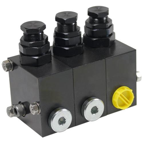
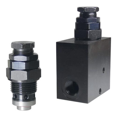
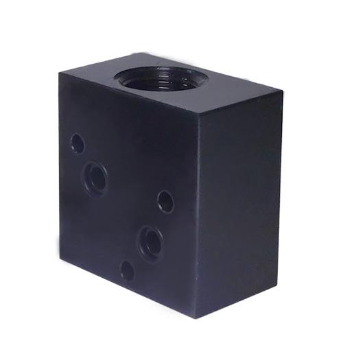
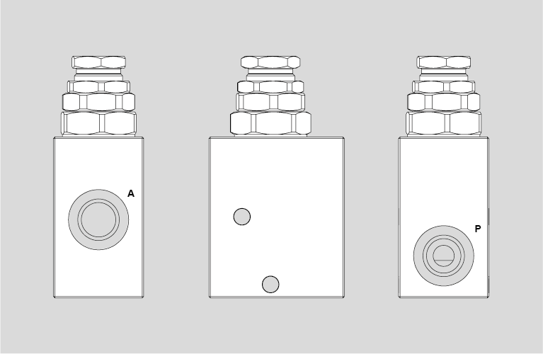
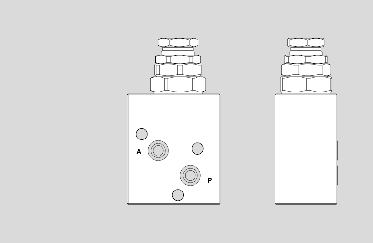
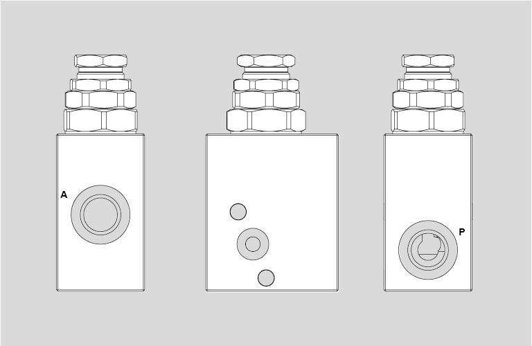
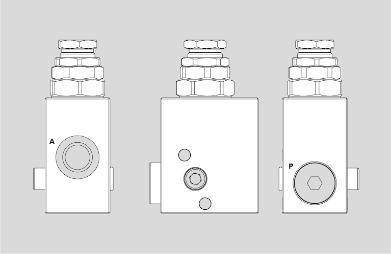
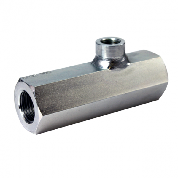
Where small clamping systems without oil supply are to be implemented, a screw pump can be integrated for pressure generation. There are two housing variations available. The screw pump with block housing and G1/4 threaded port or manifold connection and the screw pump with threaded housing.
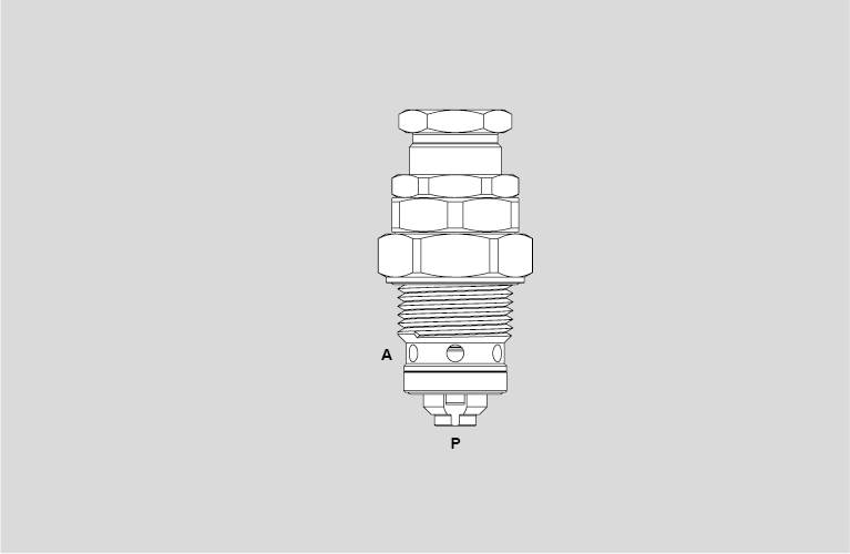
Screwing in the spindle compresses the fluid medium. The pressure within the clamping system increases. Once the operating pressure is reached, the clamping process is implemented and the workpiece is clamped. Unscrewing the spindle decreases the pressure. The clamping system de-clamps and releases the workpiece again.
-
ideal for small clamping systems without external oil supply
-
actuation of the spindle with tools possible
-
compact design
-
standard pumps and special designs available
Important information:
For filling the screw pump with hydraulic oil, the spindle should be screwed in. Then, fill in the oil through the fill port and in doing so, unscrew the spindle again. The clamping system may not contain air bubbles as these might cause pressure drop. After the filling process, the clamping system needs to be completely vented. For that, an vent screw has to be positioned at the highest point.
Screw pumps and clamping elements form a closed system. All connected components must be leak-proof in passive state. The stroke volume of the screw pump may only be to 60-70% of full capacity. This means, you should not screw the spindle up to the edge.
The clamping force can be monitored with an optional pressure gauge. To operate the spindle, also tools with torque control can be implemented. It is not recommended to use impact wrenches for that.
Data sheet 430-5
Check valves, hydraulically pilot operated
Description
These hydraulic check valves are part of the shut-off valves according to DIN ISO 1219. With a hydraulic inlet in the connection Z the blocked flow A→B can be opened. The flow B→A is permanently open. Pressure medium: Hydraulic oil 10 68 mm²/s, (ISO VG 10 to 68 according to DIN 51 519). The check valves without pilot control feature a ball as a valve element.
Application example:
The valve version with pilot control contains a spherical grinded valve piston with an integrated ball check valve. Already when opening the valve piston a throttle opening is released during the unlocking process. This dampens the pilot opening movement of the unlocking piston. Pressure surges in the load volume are suppressed by that. The pilot control ensures a lower opening pressure which is suitable especially for for swing clamp cylinders.
-
any mounting position possible
-
easy installation through pipe connections
-
dampens pressure surges in the consumer volume
-
allows low opening pressure
-
ideal for high operating pressure and consumer volumes
-
especially suitable for swing clamp cylinders
Data sheet 700-10
Design:
Shut-off valves according to DIN ISO 1219
Operating pressure:
pmax. 500 bar
Installation:
pipeline
Inst. position:
various
Pilot control:
without/with
Main passage:
A, B with G1/4 threaded port
Control port:
Z with G1/4 threaded port
Control volume:
0,15 cm³ and 0,40 cm³
Volume flow:
Qmax. 15 l/min and 55 l/min
Wrench size:
24, 32
Pressure medium:
Hydraulic oil, acc. to DIN 51524 Tl.1 up to 3; ISO VG 10 up to 68 acc. to DIN 51519
Data sheet (PDF):