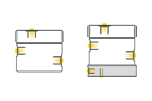
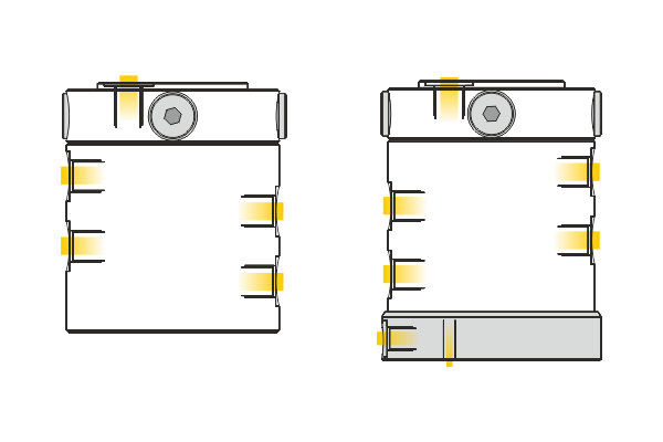
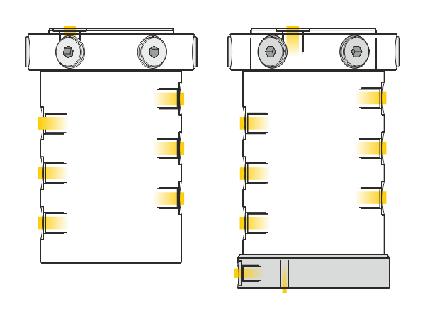
Rotary couplings without/with leakage recirculation
Description
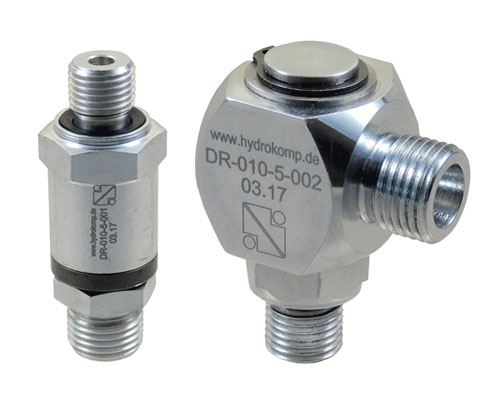
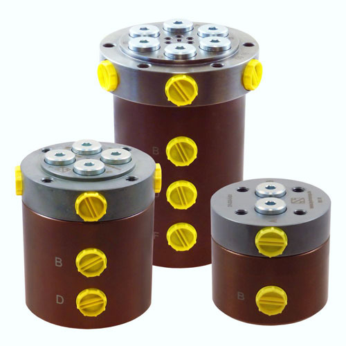
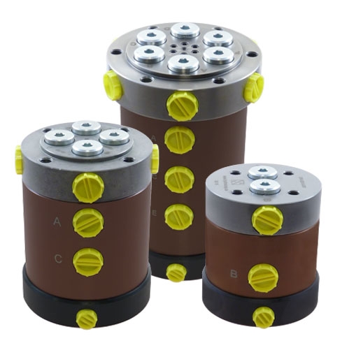
Rotary couplings transfer hydraulic oil from a fixed to a rotating machine part. The assembly is done in the rotation axis of the subassembly. Depending on the number of junction levels several single-acting or double-acting hydraulic elements can be connected. On principle, the rotary coupling is only suitable for hydraulic oil. If pneumatic shall be transferred, the catalogued elements can be used providing that the air is filtered and lubricated to guarantee seal greasing and corrosion protection.
In the design stage it needs to be considered that the rotation movement is obstructed by the seal friction. This frictional drag is pressure dependant and must be considered for the drive torque of the rotary table. Corresponding information can be found in the reling diagrams which show the starting torques existing while all junction levels are pressurised.
-
axial and radial connections in the piston
-
available without and with leakage recirculation
-
appropriate for pneumatic and hydraulic systems
-
combinable with multiple coupling systems (KDS)
-
combinable with electrical slip rings as a special design
-
standard designs and special designs available
![]()
Important operating instruction:
For the operating circumstances, operating pressure and torque must be aligned. Please see the diagrams on data sheet 500-3.
Mounting instruction:
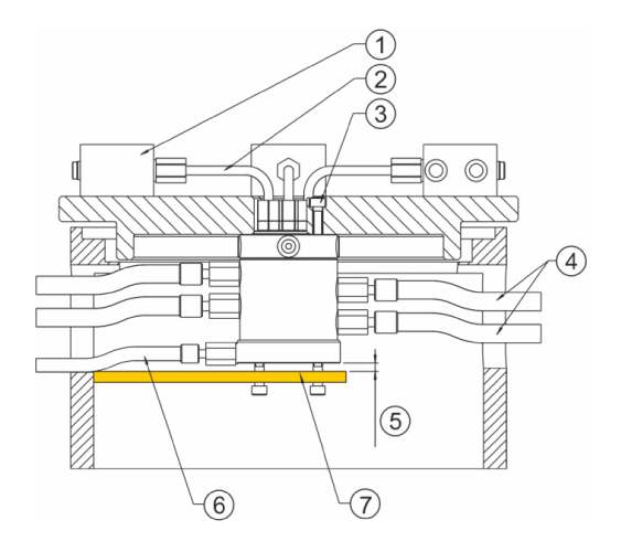
The rotary coupling must be mounted in a way that no transverse moment is effected on the standing or rotating element. It has proven to be best to screw the standing housing with its ports towards the clamping divices and to protect the rotating piston only against twisting (no initiation of bearing forces).
The line connection from the torque support to the rotating piston should be done via hoses only to avoid the initiation of torque into the housing. The rotary coupling may only be taken into operation when all junction levels are connected to the power unit in order to guarantee the necessary seal lubrication.
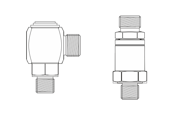
The multiple passage rotary couplings have axial and radial G1/4 threaded ports in the rotating piston. In addition, they can be connected axially at the rotating piston with O-Rings 16 x 2. In this case, please calculate the necessary screw forces of the fixing screws imperatively.
Application example:
Application examples
Multifunctional rotary coupling transfers fluid media and control signals
HYDROKOMP is forming a space saving and labour saving path. Independent of the number of clamping stations, the multi-functional rotary coupling MFD transfers the pressure and return of a fluid medium via only two channels. In addition it delivers electronic control signals to the fixture. More media lines, eg. for air or water, are optionally available for the user.
Hydraulically driven fixtures on rotary tables are normally activated directly over the rotary couplings. In addition every clamping station requires one or more hydraulic lines. The length and installation space of the rotary couplings are increased corresponding on the number of clamping stations.
With the HYDROKOMP solution an electrical slip ring transmitter replaces to a large extent the fluid lines. The work table or the fixture accepts the valve block for the clamping equipment. Instead of 6 to 24 lines, with the MFD only two lines supply all valve blocks. To control the valve blocks or the clamping stations, the slip ring transmits the electronic control signals. Their amperage can be up to 2 A and voltages up to 24 V. In this way the user saves installation space and line and leak labour. On customer request the rotary couplings can also be produced for Profibus and other applications.
HYDROKOMP produces mainly MFD rotary couplings with nominal diameters between 40 mm and 200 mm. The hydraulic pressure can be up to 500 bar and the gas or air pressure 10 bar. The rotary couplings are manufactured out of corrosion protective materials such as brass or corresponding steels.
Typical applications are welding of lorry and construction machine parts, mechanical processing of large components in rotary indexing machines or surface treatment and cleaning in several work stations. The small installation length of the rotary coupling MFD makes it easier to convey application-specific
other media, e.g. purging gas during welding or coolant lubrication during the machining process.![]()
Rotary valve coupling for hydraulics, pneumatics, water and electrical energy
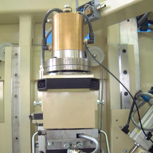
The rotary coupling shown below transmits two cores hydraulics with max. 240 bar, four cores pneumatics (10 bar) and has an electrical rotary connection which transmits 6 times 24 V with 2 A.
The electrical rotary connector controls hydraulic distribution valves through which several clamping elements clamp the workpiece hydraulically.
The max. rotational speed of the version is determined by the hydraulic pressure, the diameter of the sealing and the number of stressed sealings. The value of the friction force resulting from these parameters is the limiting factor. In the mentioned case the max. rotational speed is 25 1/min.
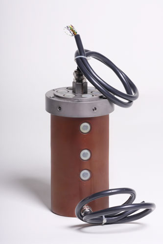
The photo below shows the electrical rotary connection mounted into the lid. To the side and the front the cables are made moisture-proof through cable fittings. Through a double sealing package a leakage connection is provided between the individual media.
12 and 6 passage rotary coupling, nominal diameter 5
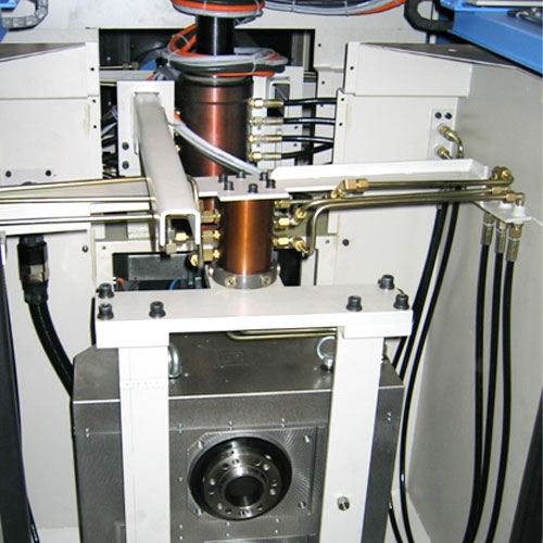
provide two fixtures with pressurized oil. The 180° pallet changer swifels both fixtures between the loading-/unloading station and the work station.
Both six passage rotary couplings rotate 360°. The twelve passage rotary coupling was designed with special seal elements to produce an insignificant torque.
Twin passage rotary coupling
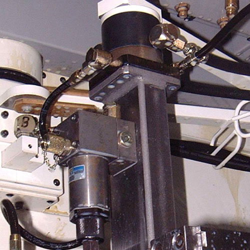
mounted in an articulated bracket construction on a 2-pallet tool machine. One rotary coupling each is mounted in the rotating axis of the two fixture pallets and allows the rotation of 360°.
The pressure supply in the rotating axis of the 180° pallet changer is done by hoses.Utilised operating pressure = 240 bar, nominal diameter 5
Data sheet 500-3
Data sheet (download here) and step files on TraceParts:
Designs:
Rotary joints with one passage:
Design:
Leakage recirculation:
Passages:
Nominal diameter:
Operating pressure:
Operating temperature:
Oil connection:
Leakage rate:
Rotation speed:
Torque:
axial and angular
without
1
5
pmax. 500 bar
from -10°C up to +60 °C
G1/4, M16x1,5
without
max. 20 1/min
unspecified
Rotary couplings with two passages::
Design:
Leakage recirculation:
Passages:
Nominal diameter:
Operating pressure:
Operating temperature:
Oil connection:
Leakage rate:
Rotation speed:
Torque:
multi conductor
without/with
2
5 and 10
pmax. 400 bar / 350 bar
from -10°C up to +60 °C
G1/4 (reflow G1/8)
30 cm³/100h (without reflow)
min. 85 1/min (50 bar)
max.53 1/min (400 bar)
min. 2 Nm (20 bar)
max.5 Nm (400 bar)
Rotary couplings with four passages:
Design:
Leakage recirculation:
Passages:
Nominal diameter:
Operating pressure:
Operating temperature:
Oil connection:
Leakage rate:
Rotation speed:
Torque:
multi conductor
without/with
4
5 and 10
pmax. 400 bar / 350 bar
from -10°C up to +60 °C
G1/4 (reflow G1/8)
50 cm³/100h (without reflow)
min. 48 1/min (100 bar)
max.26 1/min (400 bar)
min. 3 Nm (30 bar)
max.7,8 Nm (400 bar)
Rotary couplings with six passages:
Design:
Leakage recirculation:
Passages:
Nominal diameter:
Operating pressure:
Operating temperature:
Oil connection:
Leakage rate:
Rotation speed:
Torque:
multi conductor
without/with
6
5
pmax. 400 bar
from -10°C up to +60 °C
G1/4 (reflow G1/8)
60 cm³/100h (without reflow)
min. 38 1/min (70 bar)
max.28 1/min (370 bar)
min. 5,6 Nm (50 bar)
max.14 Nm (400 bar)
![]()


